
By way of illustration, we provide a new view (in Figures 07-13) of the hGH-hGH receptor interfaces analysed by Clackson and Wells. The available crystal structure consists of the ternary complex of one hGH molecule bound to two identical receptors: hGHR1 and hGHR2. Binding at the first interface, hGH-hGHR1, is high affinity while that at the second interface, hGH-hGHR2, is low affinity. The buried areas on the hGH-hGHR1 and hGH-hGHR2 interfaces are 1300 and 900 Å 2, respectively. The two binding surfaces of hGH differ in sequence while the binding surfaces of the two receptors are similar (but not identical) both spatially and in terms of the residues involved.
The pictures below are the links to stereo images of: a) the ribbon representation of the complex; b) the complex together with 2 interfaces; c) hGHR2 and hGH and interface; d) hGHR1 and hGH and interface.
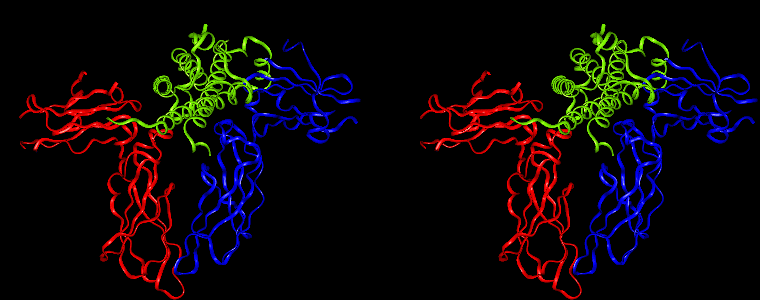
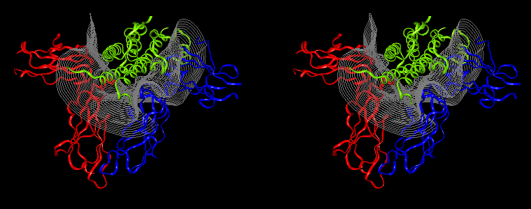
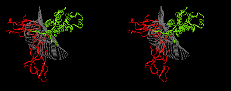
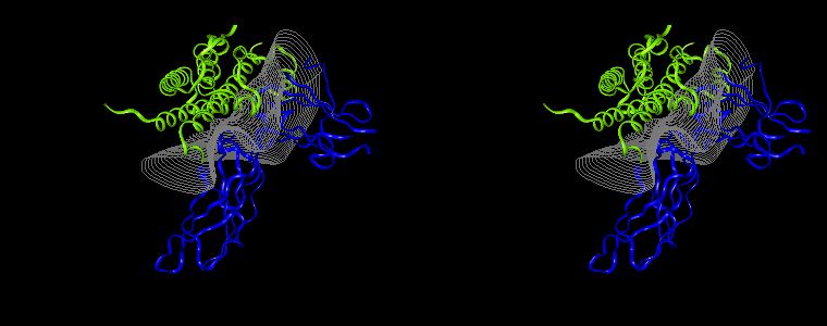
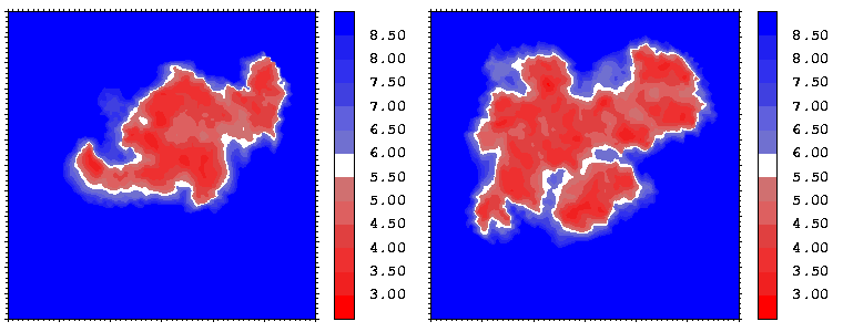
Figure 07: Mapping displaying the interprotein distances (in Å) for the hGH-hGHR2 (left) and hGH-hGHR1 (right) interfaces. The distance is computed at every interface point as a sum of the distances to the closest atoms of the two proteins. The latter distances are derived from the distance functional (1b) with atomic radii set to zero.
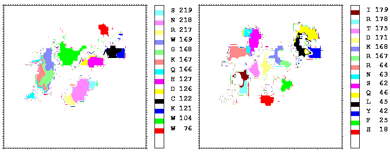
Figure 08: Mapping of the residues of hGHR1 (left) and hGH (right) onto the hGH-hGHR1 interface coloured by their number. Only the residues projecting onto more than 17 points are coloured.
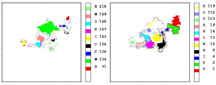
Figure 09: As figure 08 but for the hGH-hGHR2 interface.
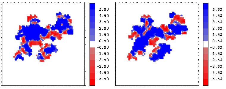
Figure 10: Mapping of the hydrophobicity properties (following Eisenberg and McLachlan) of the closest atoms of hGHR1 (left) and hGH (right) onto the hGH-hGHR1 interface. Blue regions are hydrophobic, red ones are hydrophilic.
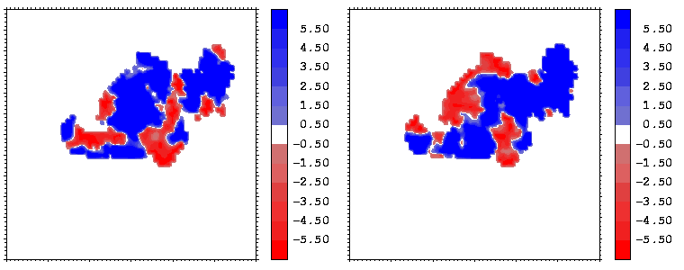
Figure 11: As figure 10 but for the hGH-hGHR2 interface.
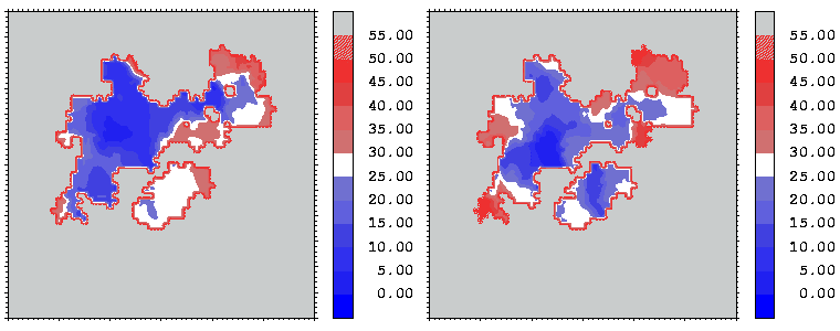
Figure 12: Mapping of the crystallographic temperature factor distribution (in Å 2) of the closest atoms of hGHR1 (left) and hGH (right) onto the hGH-hGHR1 interface. Red regions are more mobile with temperature factors above 30 Å 2; blue regions are more rigid with temperature factors below 25 Å 2
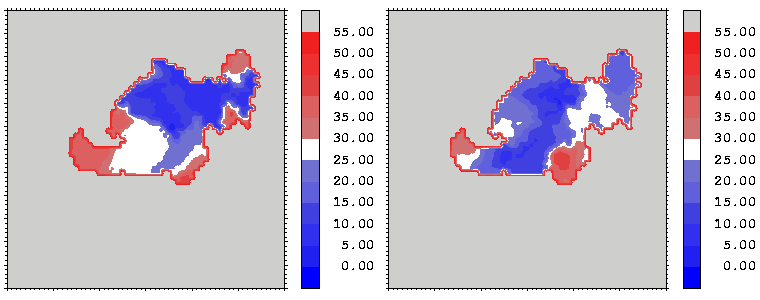
Figure 13: As figure 12 but for the hGH-hGHR2 interface.
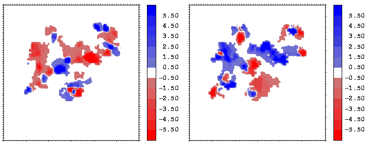
Figure 14: Mapping of the electrostatic potential (in kcal/mole/e) from hGHR1 (left) and hGH (right) on the hGH-hGHR1 interface.
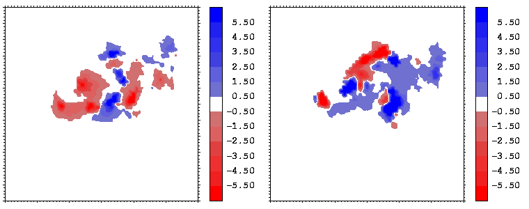
Figure 15: As figure 14 but for the hGH-hGHR2 interface.
Interfacial cavities and crevices can be identified from Figure 07. Those for which the interprotein distance is greater than about 5 Å are large enough to accommodate water molecules. As can be seen from Figures 08 and 09, the interfaces consist of residues from discontiguous parts of the sequences of the proteins. However, there are some continuous stretches of residues at the interfaces, notably, the participation of the D helix and C-terminus of hGH (residues 155-190) in interactions with the hGHR1 is readily seen in Figure 08 (right) as a more ordered region of residues with close numbers. The interface to HGHR1 is, however, not centred on this helix but inbetween two separate secondary structure patterns. On hGHR1, there are three residues that contribute large surface areas to the interface. Tryptophans 104 and 169 contact part of hGH's D helix (residues 155-184) and AB loop (residues 35-71, especially the N-terminal part of the minihelix 2, built of residues 64-70). Asparagine 218 interacts with part of hGH's A helix (residues 9-34). Experimentally it has been shown that the high affinity of the hGH:hGHR1 complex is due to the contribution of a "hot spot" on the hGHR1 receptor consisting of a small number of hydrophobic residues, including W104 and W169 (Clackson and Wells). The hydrophobic patch at the interface created by these residues is clearly visible in Figure 10. It is the largest continuous hydrophobic patch on the interface. It satisfies the description of the binding epitope as consisting of a hydrophobic center surrounded by polar moieties. An equivalent patch, due also to W104 and W169, is observed on the hGHR2 in the second (lower affinity) interface, but it differs in shape and in the arrangement of the polar residues around it. The second patch on the hGHR1 interface (formed mainly by N218 of hGHR1) also has a large buried area. However, it contributes much less to the binding energy, as revealed by mutational analysis (see Clackson and Wells ). It can be seen from Figure 12, that this patch has less hydrophobic complimentarity, being composed of hydrophilic residues of hGHR1. Moreover, it is rather mobile unlike the first patch. It is interesting that it is the mobility rather than hydrophobicity that clearly distinguishs the first patch from the second (see Figure 12 vs Figure 10) implying that the interactions between less mobile residues define the binding free energy of these two proteins. The residues forming the second patch of the interface to hGHR1 have much smaller interfacial areas on the interface to hGHR2.
The electrostatic potentials of the two proteins show a high degree of complimentarity at the interface, as can be seen from Figures 14 and 15, where regions of positive (negative) potential from one protein match regions of negative (positive) potential from the other. The electrostatic potentials were computed with UHBD. The potentials of the hormone at the two binding interfaces are similar. This is seen by comparing the right sides of Figures 14 and 15 taking into account the different transformations applied during projection: in both cases, the potential of the hormone consists of patches in the sequence: negative-positive-negative-positive (from the left to the right).
Figure 16 shows the similarity index for the potentials from hGHR1 and hGH plotted on every interface point, as well as a simple product of the two potentials. To compute the potentials used in Figure 16, the polar hydrogen atoms were simply added to the crystal structure with the HBUILD option in QUANTA. As can be seen from Figure 16, the complimentarity of the two potentials (given by negative values of the similarity index) is not uniformly distributed over the interface. There are at least 4 regions where the potentials from the 2 molecules are in conflict having the same sign and having considerable absolute values (see the right-side panel of Figure 16). To evaluate whether these result from assignment of poor hydrogen atom positions, we energy minimized the hydrogen atoms (fixing all heavy atoms) with QUANTA/CHARMM for 150 steps of steepest descent minimization. Figure 17 shows the same properties as Figure 16 for the resulting conformation.
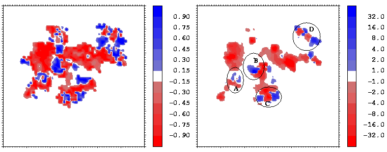
Figure 16: Similarity index
(known as Hodgkin index) as a function of the
interface point (left) and the product (right)
of the two molecular potentials for the hGH-hGHR1 interface.
Namely, given the potentials from
molecule 1,  , and molecule 2,
 ,
at the point r
of the interface, the function shown on the left-side is
,
at the point r
of the interface, the function shown on the left-side is
 and on the
right:
and on the
right:  .
There are 4 clickable regions
(A, B
,C and D)
for which 3D stereo images available.
.
There are 4 clickable regions
(A, B
,C and D)
for which 3D stereo images available.
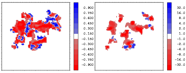
Figure 17: As Figure 16 but for the energy minimized conformation of the hGH-hGHR1 complex.
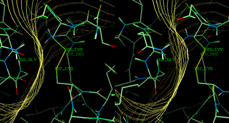
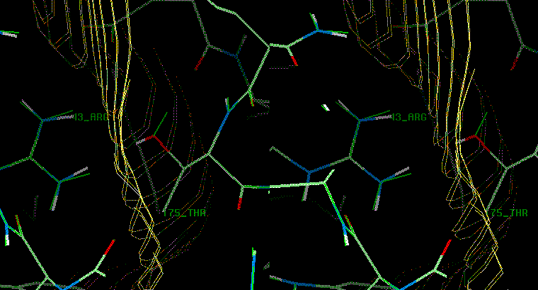
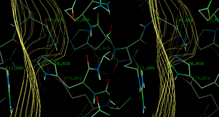
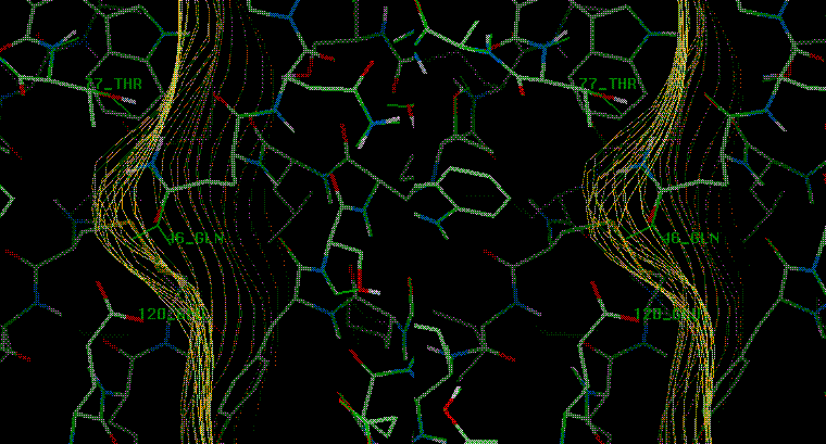
As a result of minimization, one highly non-complementary patch (B) disappeared. The other non-complementarity patches, however, remain. The conformational changes due to minimization are rather small, as can be seen by clicking on the marked patches of non-complimentarity in Figure 16 - they have links to 3D stereo images of conformations before (coloured by atom type) and after (coloured green) minimization. The receptor (hGHR1) is always drawn on the left side of the interface (yellow). Non-complimentarity in region B is removed by a conformational change in Threonine 175 of hGH, the added hydroxyl hydrogen atom of which was in obvious conflict with the side chain atoms of Arginine 43 of hGHR1. The small non-complimentarity in region A is not affected by minimization. Non-complimentarity in region D is reduced, but this is not only due to minimization: we also interchanged the NE and OE atoms of the side chain of Glutamine 46 of hGH, which, as a result, has a favourable electrostatic interaction with Glutamate 120 and Threonine 77 of the hGHR1. The interactions in region C are very complicated and remained essentially unoptimized after minimization. It is interesting that there is a correlation between electrostatically non-complimentary regions, mobile regions and the regions having a small contribution to binding.
In summary, this example shows the different features contributing to binding. The "hot spot" is a particularly rigid (blue spot in Figure 12 ) hydrophobic (blue spot in Figure 10 and white spot on the right-side panel of Figure 17 ) region of high shape complimentarity (red spot in the right side panel of Figure 07 ) involving 2 Tryptophans ( Figure 08 ) surrounded by polar residues in highly complimentary positions (best seen in Figure 17 ).